Home audio
  Audio components
  Crossover components
  Test & measurement
  DIY kits
  Accessories
  New products
  SALE
SALE  Speakers
 Amplifiers
 DAC converters
 DSP modules
 Turntables
 Streamers
 Woofers
 Tweeters
 Exciters
 Bass shakers
 Plate amplifiers
 Amplifier modules
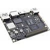 Single board computers
 Assembled crossovers
 Printed Circuit Boards (PCB)
 Capacitors
 Resistors
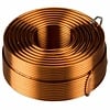 Coils
Coils Circuit Breakers
 Crossover tools
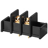 Screw terminals
 Acoustic measurements
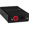 Electric measurements
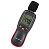 Sound level meters
 DIY amplifier kits
 DIY component packs
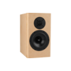 DIY speaker kit
 DIY subwoofer kits
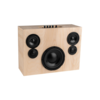 DIY bluetooth speaker
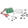 DIY electronics kits
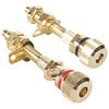 Binding posts
 Cabinet Hardware
 Cables
 Connectors
 Speaker cabinets
 Electromechanics
 Power supplies
 Speaker repair
 Workshop & tools
 Amplifier accessories
 Stands & mounts
 Gift voucher
 Books
Books New products


 Speakers
 Amplifiers
 DAC converters
 DSP modules
 Turntables
 Streamers
 Woofers
 Tweeters
 Exciters
 Bass shakers
 Plate amplifiers
 Amplifier modules
 Single board computers
 Assembled crossovers
 Printed Circuit Boards (PCB)
 Capacitors
 Resistors
 Coils
Coils Circuit Breakers
 Crossover tools
 Screw terminals
 Acoustic measurements
 Electric measurements
 Sound level meters
 DIY amplifier kits
 DIY component packs
 DIY speaker kit
 DIY subwoofer kits
 DIY bluetooth speaker
 DIY electronics kits
 Binding posts
 Cabinet Hardware
 Cables
 Connectors
 Speaker cabinets
 Electromechanics
 Power supplies
 Speaker repair
 Workshop & tools
 Amplifier accessories
 Stands & mounts
 Gift voucher
 Books
Books New products
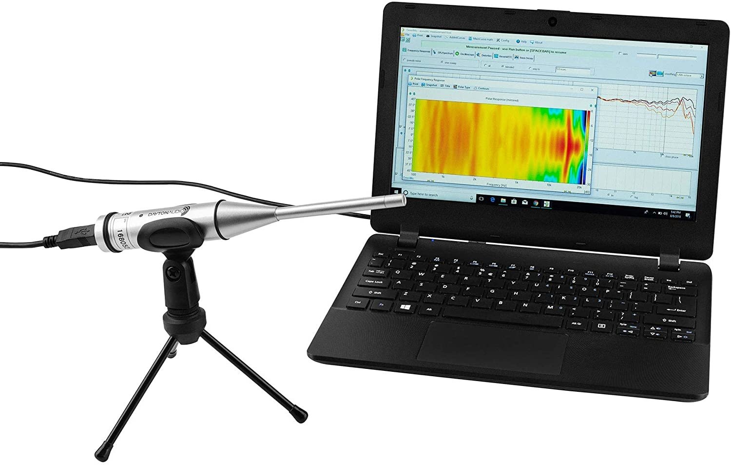
Thiele/Small parameters, a guide to the mysterious world of loudspeakers' specifications
The Thiele/Small parameters are known as the valuable specifications that determine the low-frequency performance of loudspeaker drivers. The parameters are named after two Australian loudspeaker engineers: Richard H. Small and A. Neville Thiele. After Thiele presented the paper "Loudspeakers in Vented Boxes" and Small followed up with "Direct-Radiator Loudspeaker System Analysis", the "Closed-Box Loudspeaker Systems" and "Vented-Box Loudspeaker Systems", loudspeaker engineers would not have to put trust on trial-and-error anymore. The paper presented a set of parameters to predict the electroacoustic behavior of loudspeakers in sealed and vented enclosures. Thiele and Small suggested that all loudspeaker manufacturers should make said parameters available for their products. Luckily most manufacturers did and now everyone can use these parameters to predict part of the acoustical behavior of their DIY audio design. Thiele refers to loudspeaker engineering, before the release of their paper, as a black art. With all the symbols and numbers involved, it may still look like some sort of magic. This article is written to guide you in unraveling the mystery behind the T/S parameters.
It is important to know that the system is based on circuit analysis theory. All parameters are related to equivalent circuit components like capacitors, inductors, and resistors. Therefore most parameters are closely related and intertwined through mathematical equations. The physical parameters used for the equivalent electrical circuit model are called: electromechanical parameters. They are also called fundamental parameters because they control the small-signal performance. The most practical parameters are the small-signal parameters. They are so-called because a small signal is used to measure the voice coils impedance. The impedance curve can be drafted and the resulting graph is similar to Figure 2. The data from the curve van be used to determine the small-signal parameters. The Dayton Audio Dats V3 and Audiomatica Clio Pocket 2.0 are specially intended to acquire this data fast and easy. The parameters used for calculating maximum performance are the large-signal parameters.
This article will not dive too deep into the fundamental parameters, the mathematics or the circuit analysis theory. But, please, do not be scared off if some equations pop-up; these equations will only show essential relationships between the parameters in a compact manner.
| Electromechanical parameters | Small-signal parameters | Large-signal parameters |
| Sd – Surface area | Fs - Resonant frequency | Xmax - Excursion limit |
| Mms – Moving mass | Qes - Electrical quality factor | Pe - Power handling |
| Cms – Compliance of suspension | Qms – Mechanical quality factor | Vd – Volume displacement |
| Rms – Mechanical Resistance | Qts - Combined quality factor | |
| Re – DC resistance | ||
| Bl – Force factor |
The parameters can be found (and compared) under the loudspeaker specifications on our product pages. However, there are some "hidden gems" that are not listed by all manufacturers. Those parameters do not have a direct purpose when designing an enclosure, but, some of them are important and will get some attention in this article in order to explain the relationships between each other.
The big three
Three important parameters stand out from the others because they are the foundations to calculate the others. Two of these essentials are commonly published by the manufacturer: the Resonant frequency (Fs) and the DC resistance (Re). The third notable parameter is the Maximum impedance (Zmax). All three are visible somewhere on the impedance curve. The Resonant Frequency and Maximum impedance represent the same point on the impedance curve, consequently, the impedance is maximum when the speaker reaches its Resonant frequency. The Dc resistance is visible in the impedance graph where the frequency is zero because the Dc voltage has a frequency of zero. With some calculations applied to these values other T/S parameters can be derived.
Resonant Frequency (Fs): This is the frequency at which the speaker resonates. The moving parts (cone, surround, spider & voice coil) have a certain mass and compliance (inverse of stiffness). This combination is often simplified as a mass attached to a spring.
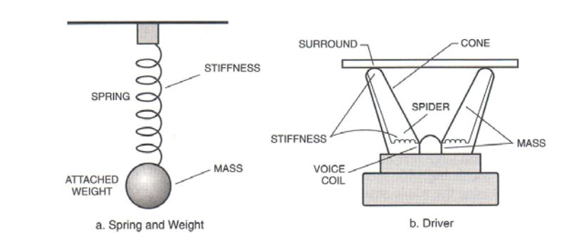
Fig. 1 The analogy between spring and speaker driver. Figure 2.3 [detail], from Alden, R. (2004); Speaker Building 201: with 11 Completely Designed Speaker Systems including a 5.1 Home Theater System, p.20.
When the mass is set to motion, the spring will stretch. A stretching spring "stores" energy and wants to return to its original state. At a certain point, the motion energy from the mass is not sufficient to stretch the string anymore. The stored energy, in the stretched string, it is strong enough to pull the mass in the opposite direction. The moving mass passes the equilibrium/rest state of the spring and causes the spring to compress. Also, the compression stores energy and eventually makes the mass move to the opposite direction again. This back and forth motion happening over and over again appear to be a resonator. The resonant frequency is the frequency at which the mass moves back and forth most freely on the spring.
DC resistance (Re): This is the DC resistance of a speaker's voice coil. Commonly Re is measured to get an estimate of an unknown (nominal) impedance. Besides giving rough estimations, Re is useful to calculate Qms.
Maximum impedance (Zmax): Beware, this is a hidden gem: not directly necessary for box calculation, but valuable nonetheless! When you take the geometric means for Re and Zmax (√ (Re x Zmax)=Rc) you can determine the side frequencies close to the resonant frequency. These side frequencies are used in the calculation of the Quality factor.
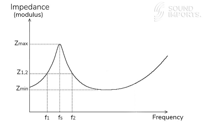
Fig.2 SB Acoustics, Technical note "Measuring Thiele/Small parameters", p.2; [Available for download]
All about Quality (Q)
Of course, Quality is something you aim for when designing a loudspeaker. Besides designing a decent system, Quality has another application in loudspeaker engineering. This is mainly referred to as the letter Q. Q is the abbreviation for the Quality factor. This unit-less measure is the inverse of damping; a higher Q means a less damped system. It practically tells how long a resonator keeps resonating. Going back to the "mass attached to a spring" analogy: Q tells how many times the mass is moving back and forth with each motion being shorter until the system is back in its rest position again. The Quality factor shows up in the following small-signal parameters:
Qms = The Mechanical Quality factor. This tells in what measure the mechanical system is damped at the resonant frequency. The mechanical system consists of moving mass (stored energy) and the suspension losses (dissipated energy).
Qes = The Electrical Quality factor. A loudspeaker is set to move through a signal driven into the voice coil. As the signal can create motion, the motion can create a (counter) signal. This is called back-emf and it opposes the flow of current throughout the voice coil near resonance frequency. The impedance is increased and the cone’s movement gets opposed.
Qts = The combined value of Qms and Qes. To calculate Qts you need the product over the sum (Qes x Qms / Qes + Qms). This can also be described as the energy that is stored divided by the energy that dissipated.
The volume of air with equivalent compliance as suspension (Vas)
The Vas parameter describes the volume of air that has the same compliance (inverse of stiffness) as the driver’s suspension. Mind that this is not a recommendation for cabinet volume; the Vas parameter describes a property of the driver"s suspension. Despite the air is all around us, it tends to not leave any impression. Therefore it is hard to grasp its physical properties. The compliance of air can be felt when air is trapped inside a balloon. If you compress the balloon with your hands, the air inside acts as a suspension. These were the small-signal parameters, except for Re being an electromechanical parameter. Up next you can find an overview of other electromechanical parameters.
Moving mass (Mms): The Moving mass is the mass of all parts that are in motion during an excursion. This also includes ‘air load’; The mass of the air against which the surface area pushes. The moving mass is an important part of the resonant frequency, but also the Q factors.
Compliance of Suspension (Cms): This is the Mechanical compliance of driver suspension. Compliance is the inverse of stiffness. It also plays an important role in the Resonant frequency, Q factors, and Vas too.
Mechanical resistance of driver suspension losses (Rms): The suspension stores energy (like with "the mass attached to a string" analogy presented at the resonance frequency section), the suspension has "losses" also. A part of the energy stored in the string is lost due to dissipative components like friction. These losses oppose the movement of the cone.
Surface area (Sd): This is the part that transfers the motion from the voice coil to the air. Because approximately half of the surrounding is moving with the cone, Sd is a bit larger than the cone area itself.
More hidden gems (acoustic components)
This might be a little difficult to understand, but the above described moving mass, suspension compliance, and mechanical resistance parameters are related to their acoustic equivalents through the surface area parameter. The equations below show that the calculations involved for the acoustic components are not that complicated:
Cms x Sd² = Cas = Acoustic compliance of the suspension
Mms/Sd² = Mas = Acoustic mass of moving parts
Rms/Sd² =Ras = Acoustic resistance of driver suspension
Simply put, the acoustic components are the link between the fundamental parameters and the small-signal parameters. For example The reciprocal of the resonance frequency (as angular frequency ω) squared is given by the acoustic compliance the times" acoustics mass (Cas ×Mas = 1/ωs²).
Force factor (Bl): This parameter consists of B x L. "B" refers to the flux density (strength of the magnetic field) and "L" to the length of the voice coil. This parameter is important because it describes the force that is created by the magnet when a signal is flowing through the coil. Bl designates the value of Qes because it’s squared value is the denominator in the Qes expression (ωsReMasSd²/ Bl²).
Large-signal parameters: The large-signal parameters are related to the largest signal a speaker can handle.
Pe = Indicates how much power the speaker can handle. Power handling indicates a thermal limit and it is limited by the amount of heat the voice coil (and surrounding structures) can dissipate. If the limit is reached, the voice coil heats up too much and will eventually take damage.
Xmax = Maximum linear excursion. Xmax tells what distance the voice coil can travel (in one way), while still staying linear.
Vd = Maximum volume displacement or peak volume displacement usually expressed in cm³. The maximum volume displacement is calculated by Xmax × Sd. Vd and it is the maximum volume of air the loudspeaker set to motion, whilst still staying linear. The volume displacement is used to calculate the acoustic output.
We hope this article shined some light on the T/S parameters and that you will be able to use them while designing your next DIY audio project.
Bibliography
- Alden, R., "Speaker Building 201: with 11 Completely Designed Speaker Systems including a 5.1 Home Theater System", Audio Amateur Press (2004).
- Gomez-Meda, R., "Measurement of the Thiele-Small parameters for a given loudspeaker, without using a box. In Audio Engineering Society Convention 91; Audio Engineering Society (October, 1991).
- Small, R.H., "Closed-Box Loudspeaker Systems", J. Audio Eng. Soc., vol. 20, pp. 798–808 (Dec. 1972); vol. 21, pp. 11–18 (Jan./Feb. 1973).
- Small, R.H., "Direct-Radiator Loudspeaker System Analysis", J. Audio Eng. Soc., vol. 20, pp. 383–395 (June 1972).
- Small, R.H., "Vented-Box Loudspeaker Systems", J. Audio Eng. Soc., vol. 21, pp. 363–372 (June 1973); pp. 438–444 (July/Aug. 1973); pp. 549–554 (Sept. 1973); pp. 635–639 (Oct. 1973).
- Thiele, A.N., "Loudspeakers in Vented Boxes," Proceedings of the Institute of Radio Engineers, Australia, 22(8), pp. 487-508. Reprinted in Journal of the Audio Engineering Society, 1971, 19 (5 & 6), pp. 382-392 & 471-483. Reprinted in R.E. Cooke (ed.) Loudspeakers, An Anthology, Vol. 1 - Vol. 25 (1953-1977), Audio Engineering Society, New York, 1978, pp. 181-204. Reprinted in Vented Loudspeakers - An Anthology, Institute of Radio and Electronics Engineers (1961).
- Thiele, A.N., "Loudspeakers in Vented Boxes, Parts I and II", J. Audio Eng. Soc., vol. 19, pp. 382–392 (May 1971); pp. 471–483 (June 1971).
Brad
Posted on friday 25 october 2024 01:12
https://diyaudiospeakers.5150.ca/thiele-small.html has some parameters not listed here.
Show more