Home audio
  Audio components
  Crossover components
  Test & measurement
  DIY kits
  Accessories
  New products
  SALE
SALE  Speakers
 Amplifiers
 DAC converters
 DSP modules
 Streamers
 Turntables
 Woofers
 Tweeters
 Exciters
 Bass shakers
 Plate amplifiers
 Amplifier modules
 Assembled crossovers
 Printed Circuit Boards (PCB)
 Capacitors
 Resistors
 Coils
Coils Circuit Breakers
 Screw terminals
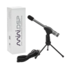 Acoustic measurements
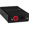 Electric measurements
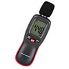 Sound level meters
 DIY amplifier kits
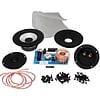 DIY component packs
 DIY speaker kit
 DIY subwoofer kits
 DIY bluetooth speaker
 DIY electronics kits
 Binding posts
 Cabinet Hardware
 Cables
 Connectors
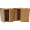 Speaker cabinets
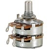 Electromechanics
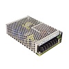 Power supplies
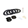 Speaker repair
 Workshop & tools
 Amplifier accessories
 Stands & mounts
 Gift voucher
 Books
Books New products
 Deals under € 100
  Deals from € 100


 Speakers
 Amplifiers
 DAC converters
 DSP modules
 Streamers
 Turntables
 Woofers
 Tweeters
 Exciters
 Bass shakers
 Plate amplifiers
 Amplifier modules
 Assembled crossovers
 Printed Circuit Boards (PCB)
 Capacitors
 Resistors
 Coils
Coils Circuit Breakers
 Screw terminals
 Acoustic measurements
 Electric measurements
 Sound level meters
 DIY amplifier kits
 DIY component packs
 DIY speaker kit
 DIY subwoofer kits
 DIY bluetooth speaker
 DIY electronics kits
 Binding posts
 Cabinet Hardware
 Cables
 Connectors
 Speaker cabinets
 Electromechanics
 Power supplies
 Speaker repair
 Workshop & tools
 Amplifier accessories
 Stands & mounts
 Gift voucher
 Books
Books New products
 Deals under € 100
  Deals from € 100
 Dayton Audio exciters
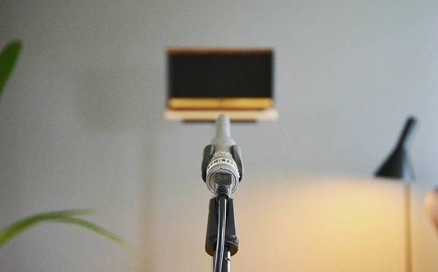
How to use measurement microphones, A basic guide to measure your (diy) audio system
You have just purchased a measurement microphone, but you are not sure how to use it. Or you are wondering if you need one and you require some more information. This blog will explain what a measurement microphone is and also contains two mini-guides. One for setting up an acoustic measurement and another about a neat measurement example: the gated measurement.
Part 1: What is a measurement microphone
Let’s start with the basics. A measurement microphone is a microphone for capturing signals you wish to analyze. In general lines, it has a simple purpose and it does not differ that much from other microphones. A measurement microphone does not measure anything by itself. It just captures an acoustic signal and transduces the acoustic signal to an electronic signal.
Yes, that’s right! A microphone is a transducer too, just as your speaker. It only transduces the other way around.
If you would stop reading here, a measurement microphone appears not to be very special and you might consider your favorite bar’s karaoke microphone fit for acoustic measurements too. But hold on; A microphone becomes a measurement microphone when it has these special features:
Connectivity
As described above, the microphone itself just captures the signals. The actual measurement requires an analyzer. Nowadays this is a computer. How do does the captured signal get to the computer?
Our most popular measurement microphones have a USB interface. The USB interface transfers the signal to your computer and supplies the 5 VDC voltage to power the microphone internal circuits. Besides being easy to use, a USB microphone has other benefits. The internal circuits allow for low noise performance, optimal hardware control, and minimize losses due to the stable digital signal transfer. You do not have any concerns about the compatibility and quality of a pre-amplifier or soundcard with a USB-microphone
USB measurement microphones
We also offer measurement microphones with analog outputs. These are still accurate, but they require a pre-amplifier and connection interface. It is common that the amplifier and interface are combined in one device, such as a USB audio interface or a soundcard.
Analog measurement microphones:
Scrolling through our Test & measurement products, you might have noticed the Audiomatica products. The CLIO pocket and CLIO 12 are the swiss army knives for loudspeaker measurements. They can measure both acoustic and electrical signals. The Audiomatica microphone is not a USB device, but instead, the included interface is. The CLIO software allows you to control the hardware and analyze both acoustic and electric measurements within the same software environment.
What else do I need besides a measurement microphone?
As the microphone only captures the signal and does not make any measurements by itself, you will need some additional tools:
Part 2: How to use a measurement microphone
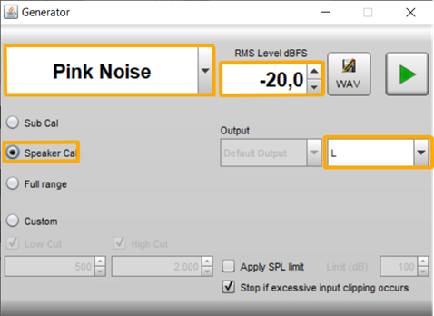
Do you have everything you need? Making a measurement is just a few steps away. Continue reading for a setup guide with REW – Room EQ Wizard

The first graph will not be very pretty; it looks more like a seismographic event than a speaker system. This is because the microphone captures the direct output, but also reflections of the signal bouncing around the room polluting the direct measurement.
A common method to make things look better is to apply smoothing. You can apply smoothing through the Graph menu in REW. A small amount of smoothing is not bad at all, but too much can distinguish the actual results. A gated measurement is a much better method for acquiring an accurate, but clean-looking graph.
Gated measurement
A gated measurement is a neat signal processing trick to make anechoic measurements in a normal environment. With this technique, you can create a time gate -or window- and force the software to only take the direct signal into account. All you need are the tools described above and a reasonable amount of space. Most measurement software all have features for gated -or windowed- measurements. Because each software is unique, we would recommend checking the manual for a specific how-to on these features. The manuals are available on our product pages.
With a gated measurement you create a time gate -or window- and take advantage of the propagating property of soundwaves, the omnidirectional property of the microphone, and powerful signal processing available in the measurement software. The fact that soundwaves travel (or propagate) allows you to make distinctions between the direct signal and its reflected counterparts. This is important as the reflections can add up or subtract on the direct signal resulting in comb filtering. The direct signal will always travel the shortest distance to the microphone. The length of your measurement gate is the time difference between the arrival of the direct signal and the arrival of the first reflection. Because sound propagates at a constant speed, you can easily calculate the extra time the reflected signals take to reach the microphone. Another easy and more accurate approach is to take a look at the impulse response graph to determine how much later the first reflection arrives. The image below shows the direct signal in orange and the reflected signal in blue:

There is a catch: A smaller measurement window results in a lower resolution and limits the lowest frequency you can measure. You can determine the lower frequency limit as follows: Fmin = 1/window length. To get a response on a wider frequency spectrum, you can combine -or merge- different measurement techniques. A near-field measurement is a perfect addition to extend the lower frequency limit of your measurement.
The gated measurement is very useful, but just one example of many things you can do with your measurement microphone. I hope this blog gets your acoustic measurement adventures started!
seac
Posted on wednesday 14 february 2024 08:48
Start by selecting a suitable microphone, calibrating it properly, positioning it correctly, recording data accurately, and analyzing results meticulously. Happy measuring!